Part II
Classical Examples and Applications
Lecture 5
Hartmann Flow
Overview
Hartmann flow is the classic liquid-metal problem that teaches three MHD lessons
at once.
-
1.
- a magnetic field can strongly reshape a velocity profile even when magnetic advection
is weak;
-
2.
- the balance among pressure, viscosity, and Lorentz force naturally produces the
Hartmann number;
-
3.
- current closure at the walls is every bit as important as the bulk momentum balance.
Hartmann flow is one of the cleanest examples in all of MHD because the formal equations and the
laboratory experiment sit very close together. In a liquid metal the assumptions of resistive–viscous MHD
are often excellent, yet the magnetic Reynolds number can remain small. That makes this problem an
ideal bridge between the general equations of the earlier lectures and a canonical laboratory
flow.
Historical Perspective
The original analysis of pressure-driven flow in a transverse magnetic field goes back
to Hartmann’s mercury experiments in the 1930s [Hartmann, 1937, Hartmann and
Lazarus, 1937]. Hide and Roberts later turned these examples into textbook MHD
problems with a clear physical interpretation [Hide and Roberts, 1962, Roberts, 1967].
Shercliff and Hunt showed how the story extends to real ducts, where sidewall current
closure creates an additional family of boundary layers [Shercliff, 1956, Hunt, 1965].
Caution
Large magnetic influence does not mean ideal MHD. Many liquid-metal duct
flows have \(\mathrm {Ha}\gg 1\) and yet \(\mathrm {Rm}\ll 1\). The magnetic field strongly brakes and reorganizes the flow, but
the flux-freezing picture developed earlier is not the right language. Here diffusion of the
induced field is fast, and wall-controlled current closure is central.
5.1 Geometry and low-\(\mathrm {Rm}\) ordering
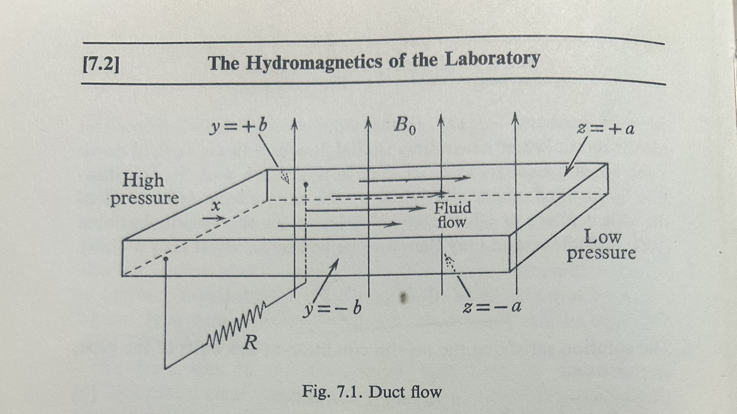
Take two parallel plates at \(x=\pm a\), infinite in \(y\) and extended along the duct direction \(z\). We impose a uniform
magnetic field
\[\B _0 = B_0\,\hat {x}, \tag{5.1}\]
and drive a steady flow in the \(z\) direction with pressure gradient \[G \equiv -\dd {p}{z} > 0. \tag{5.2}\]
The fully developed velocity is taken to be \[\uvec = u_z(x)\,\hat {z}. \tag{5.3}\]
The usual assumptions are
- steady state, \(\pp {}{t}=0\),
- incompressibility, \(\divergence \uvec = 0\),
- no-slip at the Hartmann walls, \(u_z(\pm a)=0\),
- negligible variation in \(y\) and \(z\), so all gradients are in \(x\) only,
- low magnetic Reynolds number, \(\mathrm {Rm}=Ua/\eta \ll 1\), using the definition from (2.3).
That last condition is the key difference from the flux-freezing lecture. Because \(\mathrm {Rm}\ll 1\), the magnetic field is
mostly imposed rather than advected. We therefore write
\[\B = B_0\,\hat {x} + b_z(x)\,\hat {z}, \qquad \J = J_y(x)\,\hat {y}, \tag{5.4}\]
where \(b_z\) is a small induced correction. The governing equations are just the steady specialization of the
momentum equation (1.8), the resistive Ohm law (1.9), and Ampère’s law (1.11).
5.2 Hydrodynamic limit: Poiseuille flow
If \(B_0=0\), the \(z\)-component of the steady momentum equation reduces to
\[\mu \dd {^2 u_z}{x^2} + G = 0. \tag{5.5}\]
Integrating twice, imposing symmetry \(\dd {u_z}{x}(0)=0\), and using the no-slip condition \(u_z(\pm a)=0\), one obtains the classical
plane-Poiseuille profile \[u_z(x) = \frac {G}{2\mu } \left (a^2-x^2\right ). \tag{5.6}\]
This is the profile to compare against once the Lorentz force is turned on.
5.3 Hartmann flow from the steady MHD equations
With the ansatz (5.3)–(5.4), the Lorentz force points along \(\hat {z}\) because
\[\J \times \B = J_y\,\hat {y}\times B_0\,\hat {x} = - J_y B_0\,\hat {z}. \tag{5.7}\]
and Ampère’s law gives \[J_y = - \frac {1}{\muo } \dd {b_z}{x}. \tag{5.8}\]
We can search for steady solutions to the resistive, viscous MHD equations for this geometry with a
transverse magnetic field \(b_x\). Note from \(\nabla \cdot \bm B= \frac {\partial b_x}{\partial x} = 0\) so that \(B_x=B_0\) a constant. the steady momentum equation becomes
\[-G + \frac {B_0}{\mu _0\rho } \frac {d b_x}{dz} + \mu \frac {d^2 u_x}{dz^2} = 0.\]
The \(z\)-momentum equation becomes
\[\mu \dd {^2 u_z}{x^2} - B_0 J_y + G = 0. \tag{5.10}\]
Meanwhile Ohm’s law gives \[J_y = \sigma \left ( E_y + u_z B_0 \right ), \tag{5.11}\]
Substituting (5.11) into (5.10) yields a single second-order equation for the velocity,
\[\dd {^2 u_z}{x^2} - \frac {\sigma B_0^2}{\mu }u_z = \frac {\sigma E_y B_0 - G}{\mu }. \tag{5.12}\]
This form is more useful than the fourth-order elimination because it keeps the physics transparent:
pressure drives the flow, viscosity smooths it, and the induced current brakes it.
Hartmann number.
Using \(\mu =\rho \nu \) and \(\eta =(\muo \sigma )^{-1}\), define
\[\mathrm {Ha} \equiv B_0 a\sqrt {\frac {\sigma }{\rho \nu }} = \frac {V_A a}{\sqrt {\nu \eta }}, \qquad V_A \equiv \frac {B_0}{\sqrt {\muo \rho }}. \tag{5.13}\]
Then (5.12) reads \[\dd {^2 u_z}{x^2} - \frac {\mathrm {Ha}^2}{a^2}u_z = \frac {\sigma E_y B_0 - G}{\mu }. \tag{5.14}\]
Solution.
The general even solution of (5.14) is
\[u_z(x) = A\cosh \left (\frac {\mathrm {Ha}\,x}{a}\right ) + C. \tag{5.15}\]
A constant particular solution satisfies \[- \frac {\mathrm {Ha}^2}{a^2}C = \frac {\sigma E_y B_0 - G}{\mu }, \qquad \Rightarrow \qquad C = \frac {G-\sigma E_y B_0}{\sigma B_0^2}. \tag{5.16}\]
Applying \(u_z(\pm a)=0\) gives \[A = - \frac {C}{\cosh (\mathrm {Ha})}, \tag{5.17}\]
so the Hartmann profile is \[\boxed { u_z(x) = \frac {G-\sigma E_y B_0}{\sigma B_0^2} \left [ 1- \frac {\cosh (\mathrm {Ha}\,x/a)}{\cosh (\mathrm {Ha})} \right ]. } \tag{5.18}\]
This is the basic textbook solution.
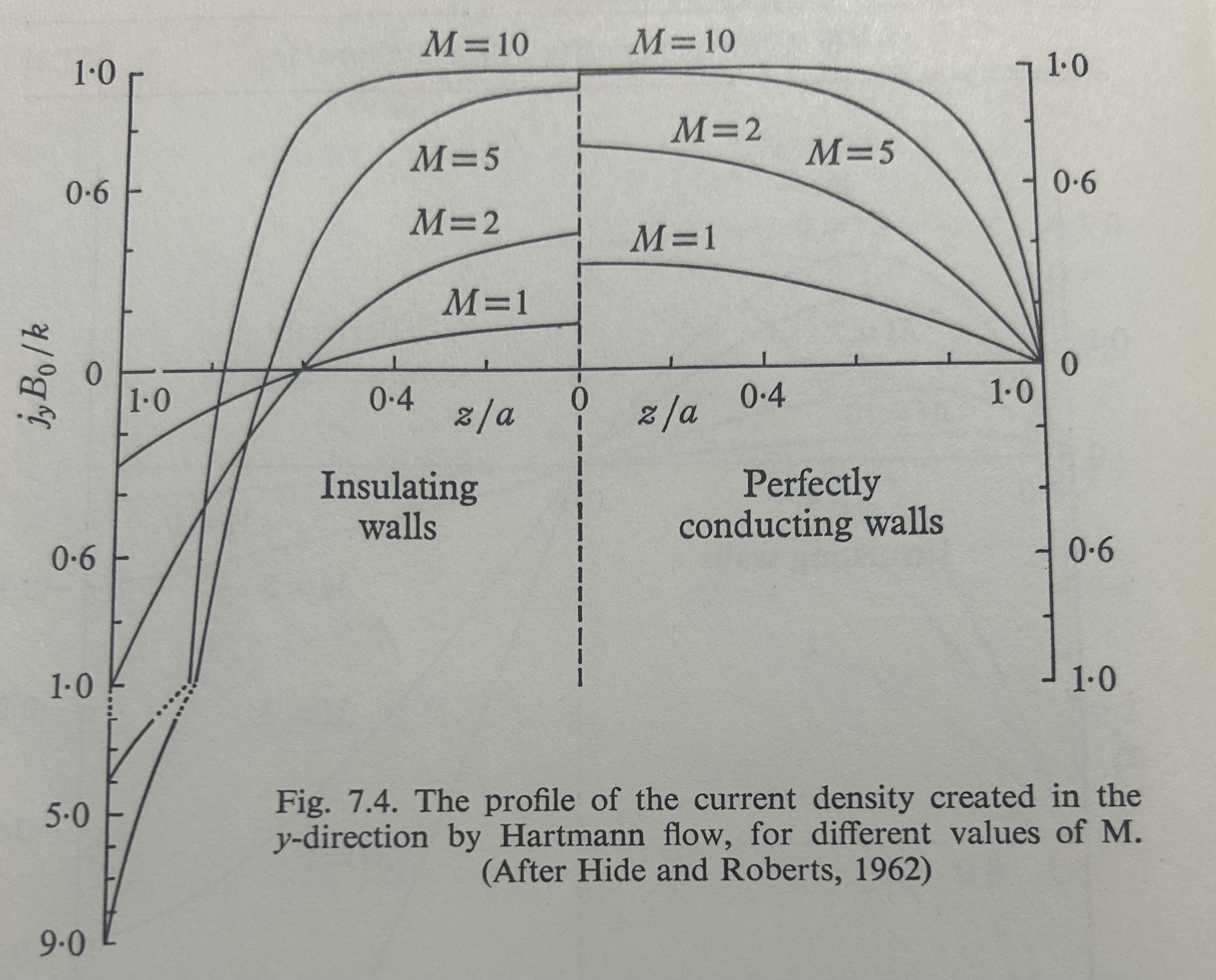
The current density follows immediately from Ohm’s law,
\[J_y(x) = \sigma E_y + \frac {G-\sigma E_y B_0}{B_0} \left [ 1- \frac {\cosh (\mathrm {Ha}\,x/a)}{\cosh (\mathrm {Ha})} \right ]. \tag{5.19}\]
Integrating Ampère’s law then gives the induced magnetic field, \[b_z(x) = -\muo \int _0^x J_y(x')\,dx', \tag{5.20}\]
with the additive constant fixed by symmetry or by a chosen reference level.
The cross-sectional average of the velocity is
\[\overline {u} \equiv \frac {1}{2a} \int _{-a}^{a} u_z(x)\,dx = \frac {G-\sigma E_y B_0}{\sigma B_0^2} \left ( 1- \frac {\tanh (\mathrm {Ha})}{\mathrm {Ha}} \right ). \tag{5.21}\]
Equation (5.21) is the most useful form for engineering estimates because it connects the pressure gradient
directly to the bulk flow.
5.4 Limiting cases and physical interpretation
Weak magnetic field: \(\mathrm {Ha}\ll 1\).
Expand the hyperbolic functions in (5.18):
\[1- \frac {\cosh (\mathrm {Ha}\,x/a)}{\cosh (\mathrm {Ha})} = \frac {\mathrm {Ha}^2}{2} \left (1-\frac {x^2}{a^2}\right ) + \mathcal {O}(\mathrm {Ha}^4). \tag{5.22}\]
Using (5.13), one recovers \[u_z(x) \simeq \frac {G-\sigma E_y B_0}{2\mu } \left (a^2-x^2\right ). \tag{5.23}\]
In the simplest conducting-wall textbook limit \(E_y=0\), this reduces to the Poiseuille result (5.6).
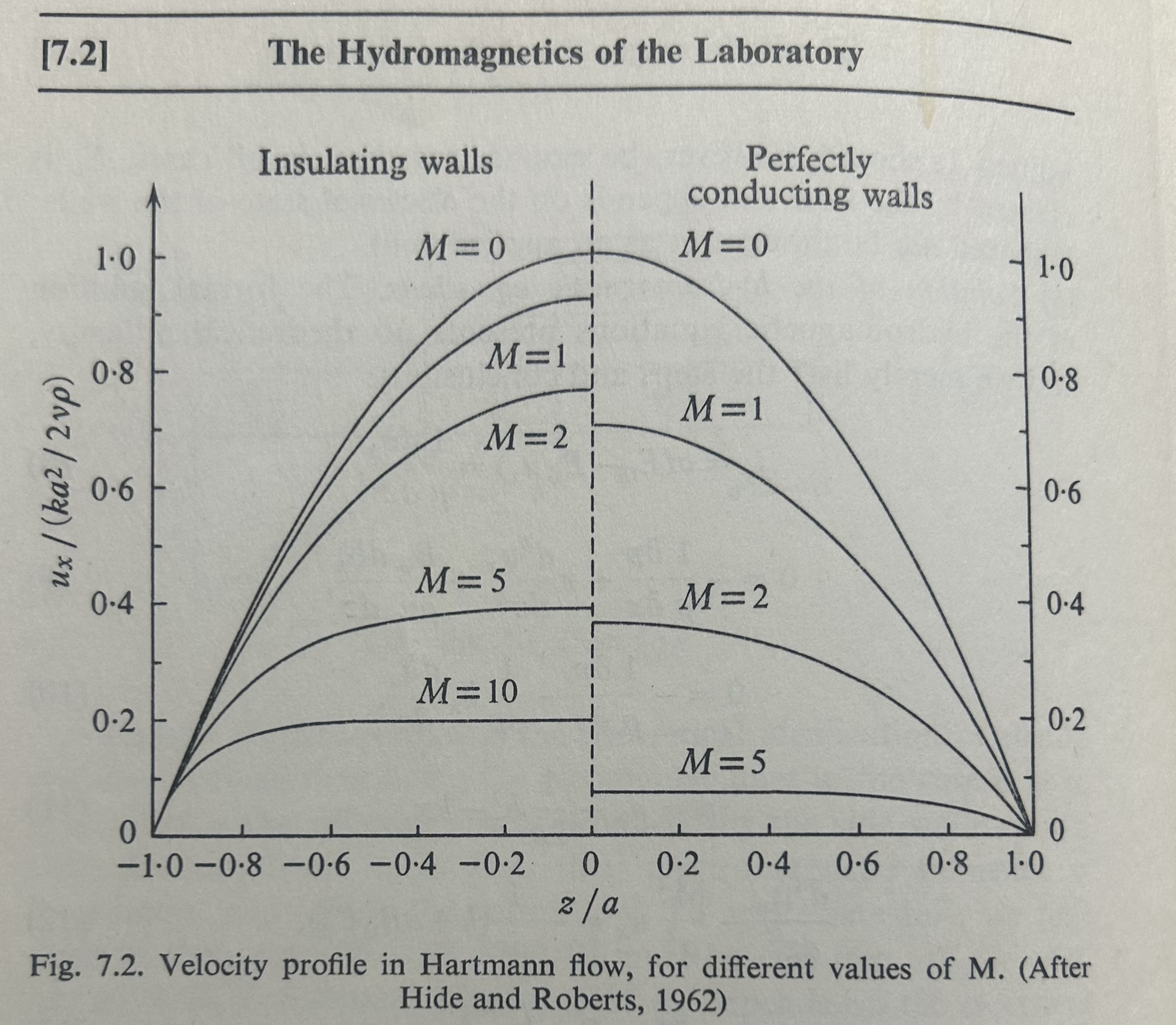
Strong magnetic field: \(\mathrm {Ha}\gg 1\).
In the core, away from the walls,
\[u_z(x) \approx \frac {G-\sigma E_y B_0}{\sigma B_0^2}, \tag{5.24}\]
so the flow becomes plug-like. The shear is expelled into thin boundary layers of thickness
\[\delta _H \sim \frac {a}{\mathrm {Ha}}. \tag{5.25}\]
These are the Hartmann layers. In the common \(E_y=0\) limit, (5.21) becomes \[\overline {u} = \frac {G}{\sigma B_0^2} \left ( 1- \frac {\tanh (\mathrm {Ha})}{\mathrm {Ha}} \right ), \tag{5.26}\]
and for \(\mathrm {Ha}\gg 1\) this implies the practical scaling \[\frac {\Delta p}{L} = G \approx \sigma B_0^2\,\overline {u}. \tag{5.27}\]
This is why liquid-metal blanket concepts can suffer enormous MHD pressure drops even when the
magnetic field is not frozen into the fluid.
What sets \(E_y\)?
Equation (5.18) leaves \(E_y\) undetermined because it is fixed by current closure. In the simplest conducting-wall
or externally short-circuited limit one often sets \(E_y=0\). For insulating sidewalls, by contrast, charge
buildup creates an electrostatic field that partly cancels \(\uvec \times \B \) and reduces the current. The figures in
Fig. 5.2 are useful precisely because they show how much this electrical boundary condition
matters.
5.5 Dimensionless numbers and why liquid metals are special
Besides the Hartmann number, the standard control parameters are
\[\begin{aligned}\mathrm {Re} &\equiv \frac {Ua}{\nu }, & \mathrm {Rm} &\equiv \frac {Ua}{\eta }, & \mathrm {Pm} &\equiv \frac {\nu }{\eta } = \frac {\mathrm {Rm}}{\mathrm {Re}}, \\ N &\equiv \frac {\sigma B_0^2 a}{\rho U} = \frac {\mathrm {Ha}^2}{\mathrm {Re}}, & S &\equiv \frac {V_A a}{\eta }.\end{aligned} \tag{5.28}\]
Liquid metals typically have tiny magnetic Prandtl number \(\mathrm {Pm}\ll 1\). That is what makes the regime so instructive:
one can have \(\mathrm {Rm}\ll 1\) while still reaching very large \(\mathrm {Ha}\) and \(N\). The field is not frozen in, but the Lorentz force still
dominates the momentum balance.
Note
Experimental perspective. This is the regime that matters for liquid-metal MHD
experiments and for fusion-blanket technology. In PbLi, sodium, or galinstan loops,
one often worries less about flux freezing than about current closure, wall conductivity,
and the pressure drop required to push the fluid through strong magnetic fields. The
experimental moral is very practical: if the walls let currents close easily, the magnetic
braking is severe; if the walls interrupt current closure, the pressure drop can be
dramatically reduced.
Interactive Hartmann-and-Shercliff Flow Explorer
Open a browser companion to the low-Rm duct-flow lecture. The app solves the coupled cross-section velocity-and-potential problem for rectangular ducts and circular pipes, lets the Hartmann and Shercliff walls be conducting or insulating, and then compares the resulting boundary layers, chord profiles, and pressure drop.
Open the Hartmann flow explorer
5.6 From parallel plates to real ducts: Hartmann and Shercliff layers
The parallel-plate solution is only the first step. In a rectangular duct the core flow remains nearly uniform
for large \(\mathrm {Ha}\), but two different boundary layers appear.
Hartmann layers.
On walls whose normal is parallel to the imposed magnetic field, the local balance remains the Hartmann
balance and the thickness is still
\[\delta _H \sim \frac {a}{\mathrm {Ha}}. \tag{5.30}\]
Shercliff layers.
On sidewalls parallel to the imposed field, currents must turn and close through broader lateral layers.
Their thickness scales as
\[\delta _S \sim \frac {a}{\sqrt {\mathrm {Ha}}}, \tag{5.31}\]
when the Hartmann number is defined with the Hartmann half-gap \(a\). These Shercliff layers are thicker than
Hartmann layers by a factor of order \(\sqrt {\mathrm {Ha}}\).
Current closure through an electrostatic potential.
For arbitrary duct cross sections it is often cleaner to solve for an electric potential \(\Phi \) rather than directly for
the current. Writing
\[\E = -\grad \Phi , \qquad \J = \sigma \left (-\grad \Phi + \uvec \times \B \right ), \tag{5.32}\]
and using \(\divergence \J =0\) gives \[\lap \Phi = \divergence (\uvec \times \B ). \tag{5.33}\]
The boundary conditions are what encode the wall physics: for a good conductor one often takes \(\Phi =\mathrm {const}\) on the
wall, while for an insulator one imposes \(\J \cdot \hat {\vect {n}}=0\), or equivalently \[\pp {\Phi }{n} = (\uvec \times \B )\cdot \hat {\vect {n}}. \tag{5.34}\]
Cross-section model solved by the explorer.
For the browser companion it is useful to write the real-duct problem in a form that keeps the cross-section
current closure explicit. This is a different coordinate choice from the earlier parallel-plate
derivation above: here the flow is still along \(\hat {z}\), but the imposed field is taken to point along \(\hat {y}\) so
that it lies in the duct cross section. Thus take the flow to be fully developed along \(\hat {z}\), with
\[\uvec = u_z(x,y)\,\hat {z}, \qquad \B _0 = B_0\,\hat {y}, \qquad -\pp {p}{z} = G = \mathrm {const}, \tag{5.35}\]
with \((x,y)\) the cross-section coordinates.
Caution
What the explorer does and does not solve. The browser companion does not
solve a separate magnetic-streamfunction problem for an induced transverse field. It
works in the standard quasi-static, low-\(\mathrm {Rm}\) limit, so the magnetic field in Ohm’s law and in
the Lorentz force is taken to be the imposed uniform field \(\B _0=B_0\hat {y}\). The unknowns are only the
streamwise velocity \(u_z(x,y)\) and electrostatic potential \(\Phi (x,y)\). Once those are known, the cross-section
current components \((J_x,J_y)\) follow directly from Ohm’s law. The only magnetic correction
subsequently reconstructed is the axial component \(b_z(x,y)\); there is no separate evolution of a
transverse or “poloidal” magnetic field in this reduced model.
With \(\uvec =u_z\hat {z}\) and \(\B _0=B_0\hat {y}\), one has
\[\uvec \times \B _0 = u_z \hat {z}\times B_0 \hat {y} = -u_z B_0 \hat {x}. \tag{5.36}\]
Then Ohm’s law gives \[J_x = -\sigma \left (\pp {\Phi }{x} + u_z B_0\right ), \qquad J_y = -\sigma \pp {\Phi }{y}, \tag{5.37}\]
so that charge conservation, \[\divergence \J = \pp {J_x}{x} + \pp {J_y}{y} = 0, \tag{5.38}\]
becomes \[\pp {^2 \Phi }{x^2} + \pp {^2 \Phi }{y^2} = - B_0 \pp {u_z}{x}. \tag{5.39}\]
The streamwise Lorentz force follows from \[(\J \times \B _0)_z = J_x B_0, \tag{5.40}\]
so the \(z\)-component of momentum is \[\mu \left (\pp {^2 u_z}{x^2} + \pp {^2 u_z}{y^2}\right ) - B_0 J_x + G = 0, \tag{5.41}\]
or, after substituting (5.37), \[\mu \lap _\perp u_z - \sigma B_0^2 u_z - \sigma B_0 \pp {\Phi }{x} + G = 0. \tag{5.42}\]
If one also wants the induced magnetic correction itself, the same low-\(\mathrm {Rm}\) ordering gives
\[\B = B_0 \hat {y} + b_z(x,y)\,\hat {z}, \tag{5.43}\]
so the only induced magnetic response kept here is the axial field \(b_z(x,y)\). Ampère’s law implies \[J_x = \frac {1}{\muo }\pp {b_z}{y}, \qquad J_y = -\frac {1}{\muo }\pp {b_z}{x}. \tag{5.44}\]
Therefore \(b_z\) can be reconstructed after the \((u_z,\Phi )\) solve from \[\lap _\perp b_z = \muo \left (\pp {J_x}{y}-\pp {J_y}{x}\right ), \tag{5.45}\]
with only an additive constant left undetermined. In the explorer this post-processing step is used to
display the induced axial field without changing the basic quasi-static solve.
Now normalize the cross-section coordinates by the Hartmann half-gap \(a\), the velocity by a reference bulk
speed \(U_\ast \), and the potential by \(a B_0 U_\ast \):
\[X=\frac {x}{a}, \qquad Y=\frac {y}{a}, \qquad U=\frac {u_z}{U_\ast }, \qquad \varphi =\frac {\Phi }{a B_0 U_\ast }. \tag{5.46}\]
If \(U_\ast \) is chosen so that the dimensionless forcing is unity, the coupled system becomes \[\begin{aligned}\left (\pp {^2}{X^2}+\pp {^2}{Y^2}\right )U - \mathrm {Ha}^2\left (U+\pp {\varphi }{X}\right ) &= -1, \\ \left (\pp {^2}{X^2}+\pp {^2}{Y^2}\right )\varphi &= -\pp {U}{X}.\end{aligned} \tag{5.47}\]
No-slip always gives
\[U=0 \qquad \text {on every wall.} \tag{5.49}\]
For conducting walls one may take \(\varphi =\mathrm {const}\), while insulating walls satisfy \[\pp {\varphi }{n} = -U\,\hat {\vect {n}}\cdot \ex . \tag{5.50}\]
Because the wall speed vanishes, this reduces to a homogeneous Neumann condition in the
fully developed laminar cases shown by the explorer. This is why the numerical problem can
be posed entirely in the cross section while still capturing the Hartmann and Shercliff layer
structure.
This is the real reason “duct flow” becomes more interesting than the parallel-plate problem: the
three-dimensional current closure can dominate the qualitative behavior.
Takeaways
- Hartmann flow is the canonical example of resistive–viscous MHD in the low-\(\mathrm {Rm}\) limit.
- The Hartmann number measures how strongly the magnetic field flattens the profile
and confines shear to boundary layers.
- The average flow is controlled not just by pressure and viscosity, but by the
wall-selected electric field \(E_y\) and therefore by the current-closure path.
- In real ducts, Hartmann layers and Shercliff layers coexist; the former are thin, the
latter broader, and both are central to liquid-metal MHD design.
Bibliography
J. Hartmann. Hg Dynamics I: Theory of the laminar flow of an electrically conducting liquid in a homogeneous magnetic field". Mathematisk-fysiske Meddelelser, 15(6), 1937.
Julius Hartmann and Freimut Lazarus. Hg-dynamics II: Experimental investigations on the flow of mercury in a homogeneous magnetic field". Matematisk-fysiske Meddelelser, 15(7):1–45, 1937.
Raymond Hide and Paul H. Roberts. Some elementary problems in magneto-hydrodynamics. Advances in Applied Mechanics, 7:215–316, 1962. doi:10.1016/s0065-2156(08)70123-6.
P. H. Roberts. An Introduction to Magnetohydrodynamics. Longmans, London, UK, 1967. ISBN 9780582447288.
J. A. Shercliff. The flow of conducting fluids in circular pipes under transverse magnetic fields. Journal of Fluid Mechanics, 1(6):644–666, 1956. doi:10.1017/s0022112056000421.
J C R Hunt. Magnetohydrodynamic flow in rectangular ducts. Journal of Fluid Mechanics, 21(4):577–590, 1965. doi:10.1017/s0022112065000344.
Guided Exercises
Work through the steps in order. The aim is not only to obtain the stated result, but also to check a useful
limit and explain the physics in words.
Problem 5.1. Hartmann flow: PbLi in SPARC
Liquid metal breeding blankets often consider Pb–17Li (“PbLi”) flowing through rectangular ducts in a
strong tokamak magnetic field. In this problem you will use Hartmann-flow scalings to estimate the MHD
pressure drop, pumping power, and the boundary-layer thicknesses that must be resolved in
simulations.
Given geometry and operating point
Consider a straight rectangular duct of height \(h=10~\mathrm {cm}\) and width \(w=1~\mathrm {m}\) carrying PbLi at bulk speed \(U=1~\mathrm {m/s}\). Assume the
magnetic field is uniform and transverse to the flow with magnitude \(B_0=10~\mathrm {T}\). Take the flow direction as \(\hat {z}\), and the
field as \(\B _0 = B_0 \hat {x}\), so that the Hartmann walls are the two faces normal to \(\hat {x}\).
Treat the Hartmann gap as parallel plates separated by \(h\), so the half-gap is \[ a \equiv \frac {h}{2} = 0.05~\mathrm {m}. \]
Assume the textbook conducting-wall limit \(E_y=0\) in Ohm’s law, so that the mean-flow relation is given by
(5.26).
Material properties (Pb–17Li, representative fusion temperature)
Use the following representative values: \[ \rho \simeq 9.3\times 10^{3}\ \mathrm {kg/m^3}, \qquad \mu \simeq 1.4\times 10^{-3}\ \mathrm {Pa\cdot s}, \qquad \sigma \simeq 1.0\times 10^{6}\ \mathrm {S/m}. \] Compute the kinematic viscosity \(\nu =\mu /\rho \) and resistive diffusivity
\(\eta = (\muo \sigma )^{-1}\).
-
(a)
- Dimensionless parameters and boundary layers.
-
(i)
- Compute the Reynolds number \(\mathrm {Re} = Ua/\nu \).
-
(ii)
- Compute the Hartmann number using (5.13).
-
(iii)
- For \(\mathrm {Ha}\gg 1\), estimate the Hartmann-layer thickness \(\delta _H \sim a/\mathrm {Ha}\).
-
(iv)
- (Optional.) Estimate the Shercliff-layer thickness \(\delta _S \sim a/\sqrt {\mathrm {Ha}}\) and compare it with \(\delta _H\).
-
(b)
- Pressure drop. For the parallel-plate Hartmann solution with \(E_y=0\), the mean speed is related to the
pressure gradient by \[ \overline {u} = \frac {G}{\sigma B_0^2} \left ( 1- \frac {\tanh (\mathrm {Ha})}{\mathrm {Ha}} \right ). \]
-
(i)
- Solve for the required pressure gradient \(G= -dp/dz\) to achieve \(\overline {u}=U=1~\mathrm {m/s}\).
-
(ii)
- Evaluate the high-\(\mathrm {Ha}\) approximation \(\Delta p/L \approx \sigma B_0^2 U\) from (5.27) and compare it with the exact answer.
-
(iii)
- Report your final \(\Delta p/L\) in \(\mathrm {Pa/m}\) and in \(\mathrm {bar/m}\).
-
(c)
- Pumping power. The volumetric flow rate is \(Q = U A\), where \(A = hw\) is the duct cross-sectional area.
-
(i)
- Compute \(Q\).
-
(ii)
- The pumping power required over a length \(L\) is \(P_{\rm pump} = (\Delta p)Q\). Compute \(P_{\rm pump}\) for \(L=1~\mathrm {m}\).
-
(iii)
- Repeat for \(L=10~\mathrm {m}\) and comment on what this implies about the value of electrical insulation in
liquid-metal blanket concepts.
-
(d)
- Interpretation and sanity checks.
-
(i)
- Why does the \(E_y=0\) assumption permit a large Lorentz force and therefore a large pressure drop?
-
(ii)
- Why do large-\(\mathrm {Ha}\) flows look plug-like in the core even though the strongest gradients are
confined to thin boundary layers?
Sanity-check hint (order of magnitude). A consistent estimate gives \(\mathrm {Ha}\gg 1\), a Hartmann-layer thickness in the
few-\(\mu \mathrm {m}\) range, and an MHD pressure drop of order \(10^8~\mathrm {Pa/m}\) for \(E_y=0\), implying pumping power of order \(\sim 10~\mathrm {MW}\) per meter of
duct at the stated flow rate.